Understanding CCP/XCP
- Influx Technology
- Sep 6, 2021
- 5 min read

CCP Protocol

CCP and XCP, or the CAN calibration protocol and the universal measurement and calibration
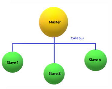
protocol, as defined by the Association for Standardization of Automation and Measuring Systems (ASAM), were designed for calibration and data acquisition on CAN from the ECUs. These are generally used in automotive vehicles for run-time automation testing. CCP is an address-oriented protocol that uses the “master-slave” concept for measurement, calibration, simulation, polling, flashing and data acquisition. Designed for various bus systems, this standard deals with moving the acquired and calibrated data continuously from the ECUs.
CCP and XCP, or the CAN calibration protocol and the universal measurement and calibration protocol, as defined by the Association for Standardization of Automation and Measuring Systems (ASAM), were designed for calibration and data acquisition on CAN from the ECUs. These are generally used in automotive vehicles for run-time automation testing. CCP is an address-oriented protocol that uses the “master-slave” concept for measurement, calibration, simulation, polling, flashing and data acquisition. Designed for various bus systems, this standard deals with moving the acquired and calibrated data continuously from the ECUs.
CCP supports the following functions:
It handles multiple nodes on a CAN Bus.
Read/write data to the ECUs internal memory.
Synchronous cyclic data acquisition from an ECU.
Simultaneous data acquisition and calibration.
Handles both small 8-bits microcontrollers and ECUs with high performance.
In CCP, communication is initiated when the master sends commands to the slave. For so, it uses generic commands.
These generic commands are not node-specific.
Every node/module must have an individual station address.
Before any commands can be sent, a logical connection between master and slave needs to be set up.
Until the master sends a disconnect command or if the master decides to connect to another slave node, the current connection will persist.
Once the connection is established, the master controls the entire communication between the master and slave.
A reply message from the slave containing data or error codes is present after every message from the master.
CCP Protocol
The universal measurement and calibration protocol or XCP acts as a single master in the

measurement and calibration system, and the PC or the ECUs operate as slaves. In the automotive world, XCP is used for measurement and calibration in pre-production vehicles and test bench for combustion engines, gearbox, climate control etc.
The initial protocol CCP was upgraded to XCP to meet the high demand for ECU resources on the network and increase data transmission to its maximum. XCP was introduced. Here ” X” in XCP stands for the variable and interchangeable transport layer.
Like CCP, XCP is an address-oriented protocol that uses the “master-slave” concept for measurement, calibration, simulation, polling, flashing and data acquisition. Designed for various bus systems, such as FlexRay, Ethernet, CAN, CAN FD and many other high-performance platforms. XCP is subdivided into protocol and transport layers.

The primary aim behind the development of XCP was to achieve as lean implementation in the ECU as possible and high scalability of features and resource utilisation.
XCP supports the following functions:
Implements 8-bit microcontrollers for CAN or SCI with few resources.
It exploits the full potential of FlexRay or Ethernet on high-performance platforms.
Reduce high demand for ECU resources.
Support maximum data transmission over the communication network.
It includes synchronous data acquisition and simulation.
Read/write access on calibration data.
Perform memory page management.
Support asynchronous and asynchronous interfaces.
Serve as a standardised interface to analogue measurement.
CRO and DTO messages in CCP/XCP
In CCP/XCP, only two types of messages are required, Command Receive Object (CRO) and Data Transmission Object (DTO). These messages are determined by a configuration file, “A2L file”, as defined by the ASAM MCD 2MC/ASAP2 standard. This configuration file is used to configure the master. The A2L file may also sometimes contain information about the slave memory organisation.

CRO: These are the messages sent from the master to slave. These contain instructions. Here the first byte is reserved for command code (CMD). The CMD describes the purpose of the message. The second byte is reserved for the command counter (CTR). The CTR is used for keeping track of the communication. It is sent in return in the DTO message from the slave. Bytes 2-7 are reserved for data parameters depending on the command code. A message is always 8 bytes long, and bytes that are not defined are considered as do not care.

DTO: These are the messages sent from the slave to the master as a receipt of receiving a CRO message and is used for data acquisition.
The first byte in the message is called PID (Packet ID). The value of the PID describes the message type. There are three types of messages:
0xFF, command return message (CRM), if the DTO is sent as a receipt of a CRO message.
0xFE, event message, if the DTO reports internal slave status changes to invoke error recovery or other services.
0 – 0xFD, data acquisition message (DAQ). This PID has the value of an ODT (Object Descriptor Table), which is described later.
CRO and DTO messages in CCP/XCP
CTO: Command Transfer Object. DTO: Data Transfer Object.

In addition to supporting other transport layers, XCP protocol contains many functional improvements, such as:
Synchronous data stimulation.
Better resource utilisation in the ECU.
Optimised communication by block transfer commands.
Plug and play configuration.
Support startup measurements.
More precise measurement data acquisition by measuring the timestamps in the ECU Slave.
Allows a client to access memory on the ECU using a format defined in a separate A2L file.
Data Acquisition: The master device can initiate the data acquisition from the slave device. Data is sent from the slave with special DAQ-DTOs. The data bytes are organised in DAQ lists which consists of several ODT lists. An ODT list contains up to 7 pointers to memory addresses in the ECU where data is stored. Besides pointers to memory addresses, and ODT list can contain an address extension and the number of bytes to be sent. All slave devices don’t handle data elements longer than one byte, and it is up to the master to solve this task by splitting the data into single bytes.
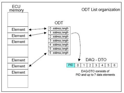
DAQ-DTO consists of a PID and the data elements to which the memory points are in the ODT list point. The PID number (usually the same as the ODT list) has a value between 0 and 253 which means there can be only 254 ODT lists simultaneously.

The CCP specification allows several DAQ lists, which can be simultaneously active. The master initiates transmission of DAQ lists through a START_STOP command. Data bytes in the ODT lists are sampled in the slave device and then sent on the CAN bus in DAQ-DTOs. If the slave receives a new START_STOP command before the ongoing DAQ cycle is finished, there are two ways to react. The new DAQ command is started, and the ongoing is terminated, or the ongoing cycle is finished, and the new is ignored. Both methods have advantages and disadvantages, and the CCP specification doesn’t say which one to choose.
CRO and DTO messages in CCP/XCP
Influx brings you a complete range of Rebel dataloggers that allow vehicle engineering testing with CCP/XCP on CAN. The ScreenShot below displays the communication settings taken by Infulx’s DiaLog (software) from the A2L file.

Moreover, the Rebel range offers advanced protocol functionality such as CAN 2.0 monitoring, J1939, CCP, XCP on CAN, OBD2 and UDS. For more details on this, please click here.


Comments